Both areas have the same number of dots, but their appearance is different. This may occur due to vibration in the print bar or miscommunication between the print bar and the paper transport which results in lack of synchronicity in the timing of jetting. In this scenario, the jetting may not compensate for variation in transport speed, meaning that droplets may miss their normal jetting sequence.
To diagnose the source of the banding, begin by identifying the characteristics of the bands, as these may be related to the two typical causes detailed below. Begin your diagnosis with the table below to isolate the cause of the banding.
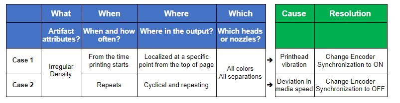
| Case 1: When banding is noticeable and the encoder synchronization control is OFF |
In this case, the encoder synchronization control is working properly to correct the deviation in the feed speed but the relative speed of the printhead and the print media is still shifting, resulting in banding. Once the effect of the feeding speed deviation is excluded as a possible cause, the likely culprit is external vibration causing minute shifts in the printbar position.
To identify the possible vibration, determine if there are devices near the feed area, as they can be sources of the external vibration. A common process is:
- Analyze the frequency of the banding on the printed media or the device vibration waveform.
- Identify the vibration source, which may include devices near the feed area
- Remove it.
- Test again.
Continue this process until all vibration sources have been considered and removed, noting each time whether the banding issue has been resolved.
| Case 2: When banding shifts when encoder synchronization control is OFF |
If banding shifts when the encoder signal is turned ON or OFF this is an indication that the trigger signal may be the cause of the banding due to a deviation in the feed speed relative to printbar jetting.
For example, if the physical distance between where the trigger signal is generated and where the printhead (jetting position) is elongated, the actual ejection timing can be off due to flapping or expansion/contraction of the print media. This is a common phenomenon with roll-type printers.
To resolve, begin by shortening the physical distance between the trigger signal and the printhead. Alternatively design halftone-screening pattern in the same frequency that corrects the deviation of the dot position assuming these are constant. If the pattern frequency is not consistent a screening solution will not resolve the issue.
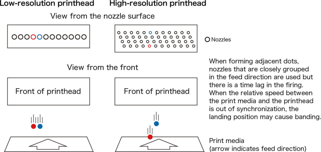
As described in Case 2, timing of the drops is critical to print quality. Figure 3 below shows the difference in how a low-resolution, single channel printhead drops ink synchronously, while a high-resolution printhead has a two-dimensional nozzle channel pattern that offsets the nozzles (shown on the right) in the feed direction. With a single channel printhead, the drops are all triggered in a similar way. Ejecting the ink onto the print media using a high-resolution printhead requires timing coordination between the different jetting rows. That time delay ensures uniform droplet positioning.
For example: If the media moves at a speed of 0.5 milliseconds, it is necessary to eject the ink droplets with a time shift of 10ms compared with the preceding channel jetting time. If the relative speed between the print media and the printhead changes by 10%, the landing position within this 10ms, will be shifted by as much as 0.5 mm in the feed direction resulting in banding.
Fujifilm has a wide range of technologies and an experienced team that can support your development and help you to identify, diagnose and eliminate these artifacts. Watch for our future publications regarding challenges in inkjet technology integration. In addition, if you have specific questions about banding or you would like to discuss specific challenges in your printer product development, please contact us using the inquiries form provided via the Link below.
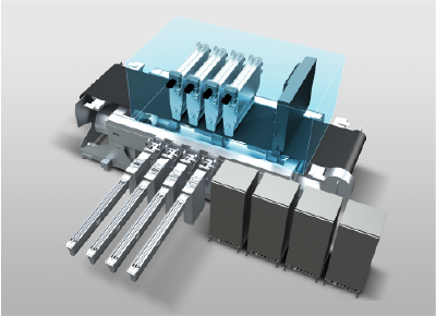
FUJIFILM SAMBA® JPC: A set of inkjet components revolutionizing the speed of 1,200 dpi, high-resolution digital printer development.